")
")
 |
 |
 |
- Details
- Hits: 4453
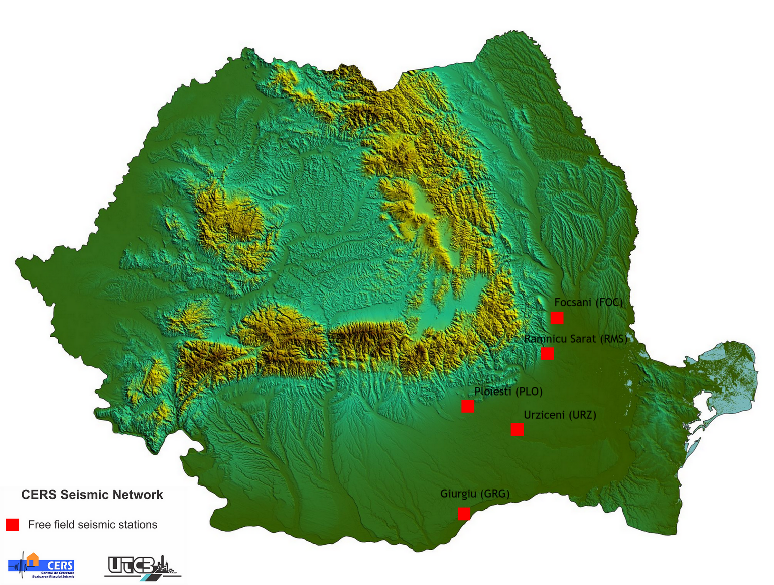
The seismic network donated by JICA was installed in 2003 by staff of OYO Seismic Instrumentation, Building Research Institute (Japan) and of the National Center for Seismic Risk Reduction (NCSRR) – the implementing agency in Romania of the JICA Project.
Seismic network is composed by:
-
Five free-field seismic stations ETNA Kinemetrics (outside Bucharest) for ground motion attenuation analysis (installed on the SW direction starting from Vrancea epicentral area toward Bucharest in Focsani, Ramnicu Sarat, Urziceni, Ploiesti and Giurgiu)
-
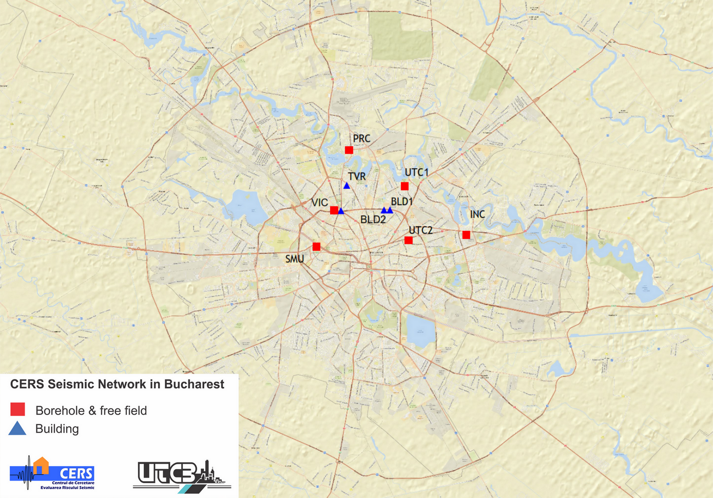
Six seismic stations Kinemtrics K2 for site effects assessment (in Bucharest) with sensors at ground surface (close to free-field conditions) and in boreholes at two levels of depth: the first level at about 30m depth and the second level between 50m and 153m depth. At all the stations the soil profile of the boreholes is known, and NCSRR and Tokyo Soil Corp. (Japan) performed down-hole tests with JICA donated equipments.
-
Four seismic stations Kinemetrics K2 for structural monitoring with sensors at top and bottom of the buildings
For all seismic stations sampling rate is set at 100Hz, pre-trigger time is 30s, post-trigger time is 60s, and full scale is ±2g for all stations. For Kinemetrics stations time is set by GPS.
- Details
- Hits: 8252
The structural testing equipment consists of a steel reaction frame with digitally controlled hydraulic loading system and digital data acquisition system.
Lateral load is applied using two identical hydraulic jacks with 200 mm maximum stroke and ±1MN loading capacity. Vertical load is applied using a hydraulic jack with 100mm maximum stroke, 2MN compression capacity and 1MN tension capacity. To restrict the rotation and the out of plane movement of the loading beam a pantograph is installed in between the reaction frame and the loading beam. Three load cells are used to measure the horizontal and vertical loads. Pairs of linear displacement transducers are installed to measure the horizontal and vertical displacements in between the top and bottom stubs.
The following load combinations are possible: bending with shear and bending with shear and axial load. The maximum weight of tested specimens is 7.0t and the maximum dimensions of the tested specimens are 2.50m by 3.00m.
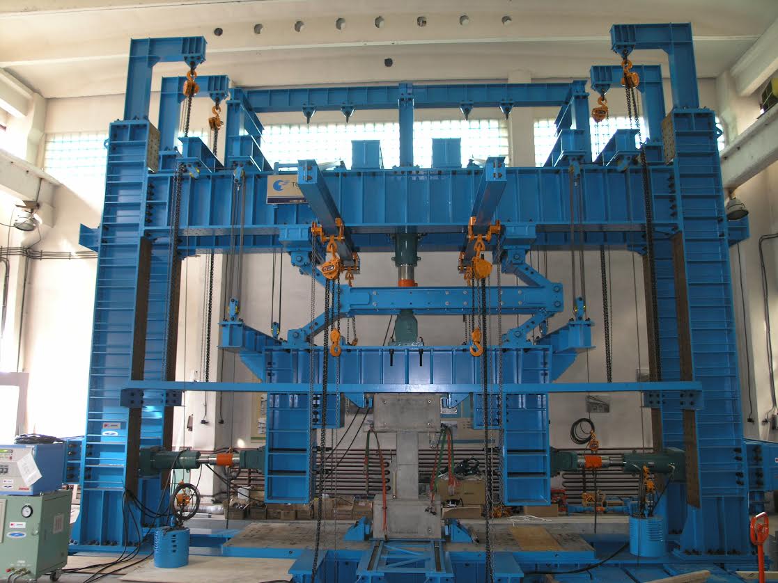
The structural testing equipment was provided in 2004 by the Japanese International Cooperation Agency, within the Romanian-Japanese technical cooperation project for seismic risk reduction.
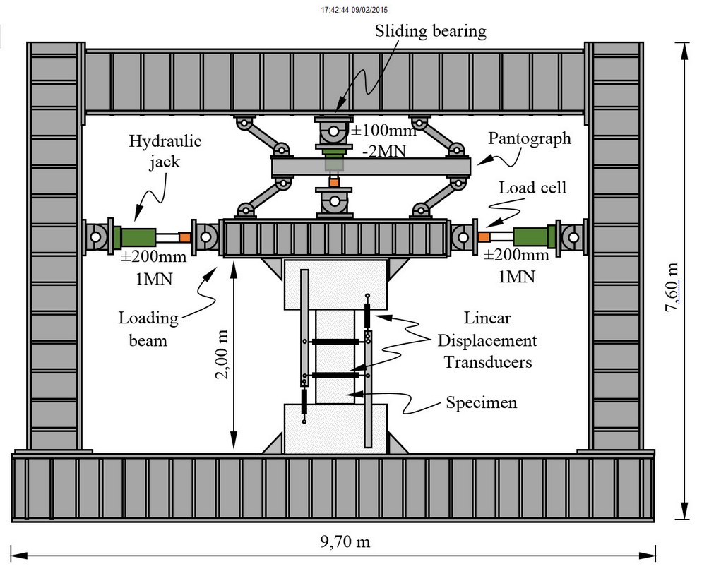
Test setup for a squat masonry or concrete wall with restricted rotations at both ends of the specimens. Maximum height of the specimen 2.45m (including the top and bottom stubs)
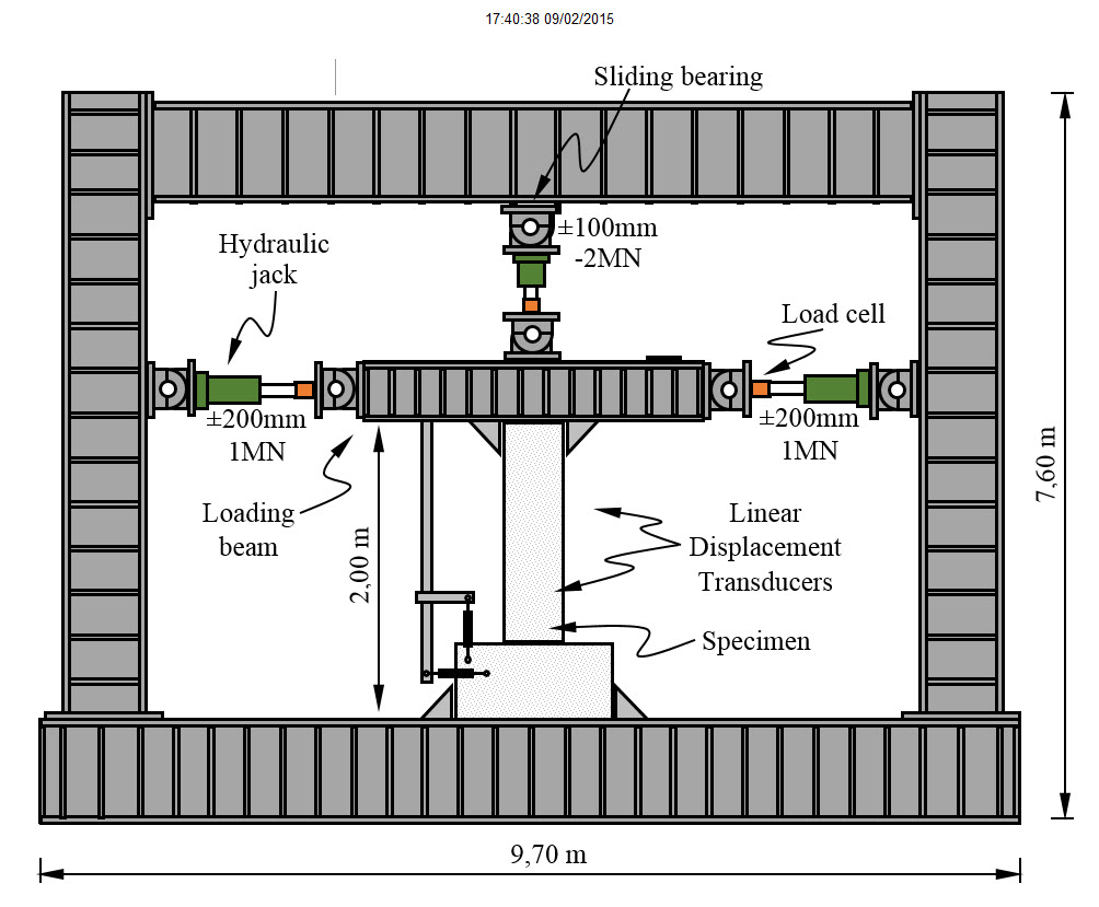
Test setup for a cantilever column, with restricted rotation at the bottom end and free rotation at the upper end. Maximum height of the specimen 2.45m (including the top and bottom stubs)
- Details
- Hits: 11018
The laboratory soil testing equipment consist of a Triaxial Testing Apparatus Model No. DTC-367 - Seiken Inc., which fulfills all the requirements of The Japanese Geotechnical Society (2000).
The triaxial equipment can solve the following types of problems:
- static problems with strain level at 10-3 or greater (the main concern regarding the static problems is used to evaluate the degree of safety of foundations or soil structure against the failure);
- dynamic problems with soils subjected to a strain levels as small as 10-6 (used to evaluate the soil strength in comparison with stresses induced by external loading and the settlement of ground or structures associated with the deformation of soils.
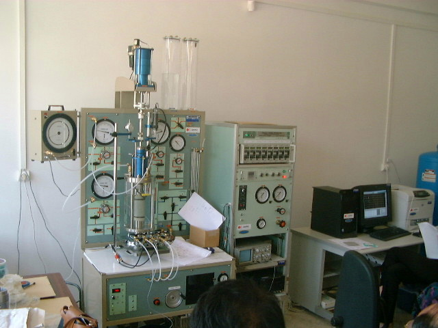
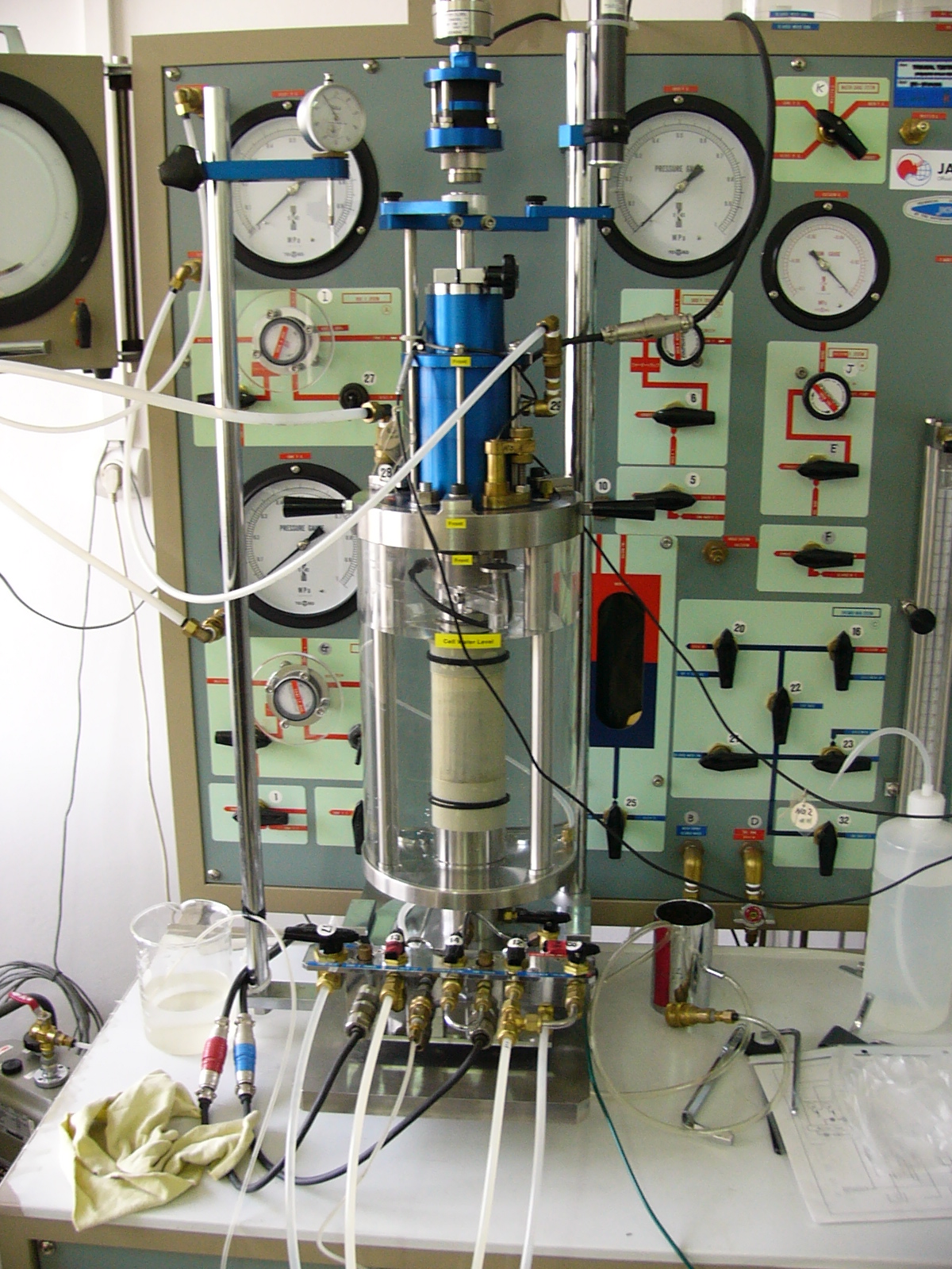
The equipment has the following specifications and components:
- Triaxial Cell equipped with Water-proof and Pressure-proof Load cell 3kN
- Air bushed piston of extremely small friction
- Specimen Size: Diameter 50mm X 100mm
- Lateral Pressure Capacity: Max. 1Mpa
- Axial Loading Capacity: 5kN
- Vertical Pressure Loading Unit with Air & Water Panel
- Static Vertical Loading: Electric Strain Control by Mechanical jack, Capacity 5kN, (0.002 – 2 mm/min. Step-less variable type)
- Dynamic Vertical Loading: Stress Control by Pneumatic bellofram cylinder, Capacity 2kN
- Lateral & Back Pressure Loads: Both 0 – 1Mpa by Air regulators, Manual operation
- Volume Change Apparatus: Double tube burette type 25ml
- Master Gauge: Dia.200 ×1Mpa, Min. div. 1/500
- Pneumatic Sine Loader
- Electric-Pneumatic pressure conversion type & Loading control type
- Range of Vibration: 0.001 – 2 Hz
- Loading Wave: Sine wave
- Setting of Load: Both Static Bias & Dynamic loading are 1000 Division, Potentiometer type
- Loading Number of Times: Random Preset type with 6 Figures Digital Counter
- Pneumatic Pressure Capacity: 1Mpa
- Electric Power Source: AC Single phase local voltage
- Transducers & Amplifier
- Inner Load Cell: 2kN or 500N
- Large Vertical Displacement Transducer: 25mm
- Pores Water Pressure Transducer: 1Mpa
- Small Vertical Displacement Transducers (gap sensors) +/- 1mm & Amplifiers
- Lateral Pressure Transducer: 1Mpa
- Volume Change Transducer: 25ml
- Amplifier suitable for the above converter: 5ch.
- Details
- Hits: 9724